Info: I do not own this machine anymore, therefore my ability to answer your questions is limited.
The problem
In 2017 I bought a refurbished HP z820 Workstation sporting 2 unreasonably powerful electric heaters in the form of Intel Xeon E5-2687W v2 and comfortable 128 GB ECC memory. Since I used the machine for offloading CPU-based raytracing jobs only, I was able to store it in a more remote part of my apartment where it did not really bother me.
Now, the jobs I did back in the day are all done, and I don’t use the machine that often anymore. A shame really. Or, at least, I used to not use it anymore. But since my daily driver – a very particular combination of a Ryzen 5 1600, G.Skill RAM and an RX 480 – doesn’t play too well together with Linux kernel 5.x (Manjaro), presenting me with totally cool random reboots, system freezes and the like, I needed to look for alternatives.
So, the idea was formed to use the z820 instead. If it just wasn’t for the noise level. Ohh, the noise this thing makes. You see, I understand that the 2x 2687W v2 with 150W TDP each, high current VRMs, 128 GB ECC DDR3 and an RX 480 need proper cooling. But running this beast of a machine in its current state and under my desk was just out of the question.
An avid PC builder and quiet-loving enthusiast myself, I looked for a solution.
The situation
A typical HP z820 is cooled by:
- 2x 92mm axial case fans behind the drive cage, in a pull-configuration
Nidec T92T12MS3A7 – 57 A03
HP ASSY PN 647113-001 REV A
12V DC, max. 0.35 A
each 4-Pin, presumably standard pinout PWM driven - 2x 92mm axial case fans at the rear of the case in a push-configuration
Delta QUR0912VH
HP ASSY 644315-001 REV 0A
12V DC, max. 0.6A (-BL3H)
bundled together via a proprietary 6-pin contraption, presumably PWM driven - 2x 80mm axial fans in the front of the PSU, in a pull-configuration
Delta QUR0812SH
12V DC, max 0.5A (-HE00)
each 4-pin, presumably non-standard pinout, PWM driven
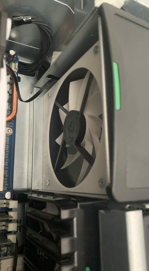
and this monstrosity here:
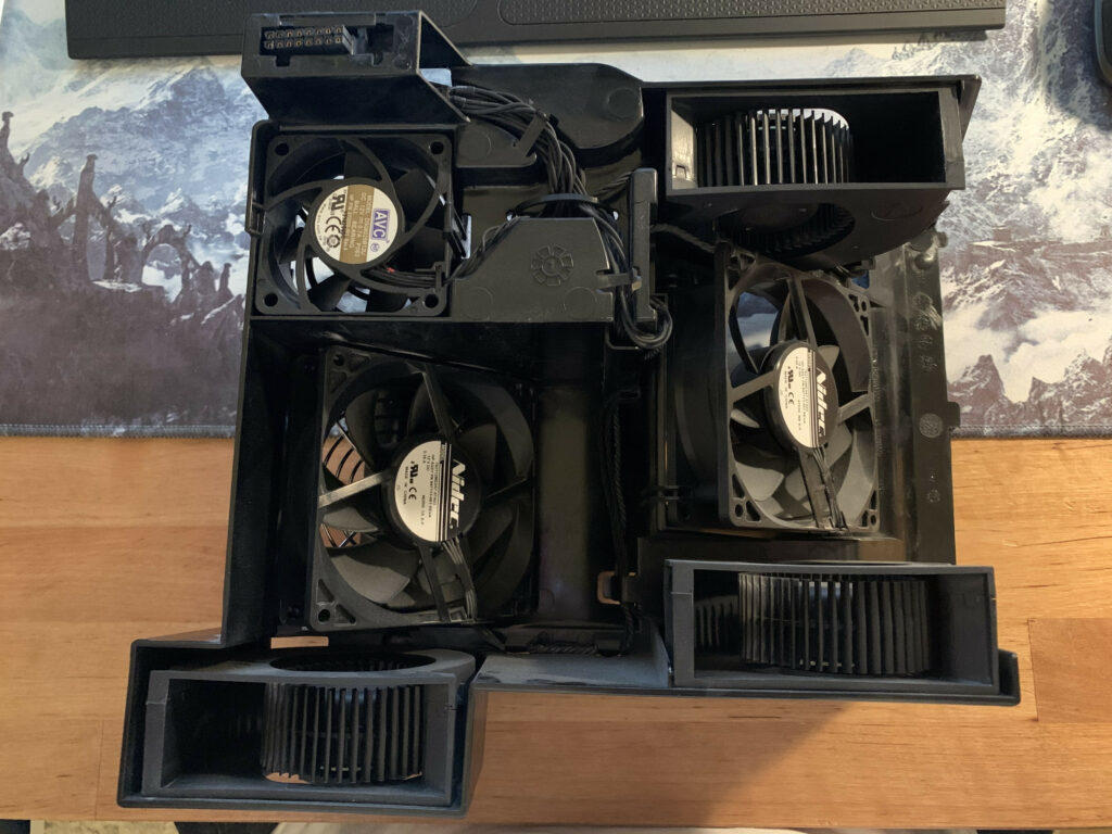
This is HPs idea of a wholly integrated fan assembly (‘shroud’) that holds 6 fans in total and is designed to cool the CPU, RAM banks and VRMs altogether. It is made up of
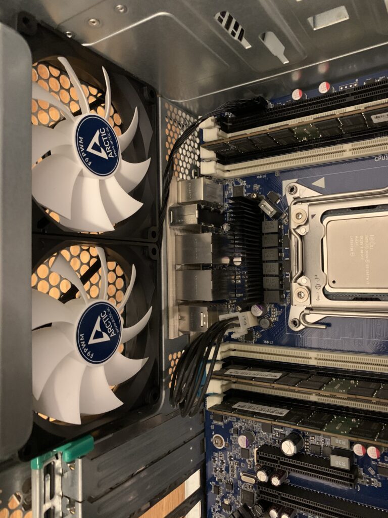
- 2x 92mm axial fans, designed to cool the CPUs
Nidec T92T12MS3A7 – 57 A03
HP ASSY PN 647113-001 REV A
12V DC, max. 0.35 A
each 4-Pin, presumably standard pinout PWM driven - 3x OEM radial fans, Delta BUB0712HF, designed to cool the RAM banks
HP ASSY PN 670051-001 Rev A
12V DC, max 0.86 A (-BE04) - 1x 60mm axial fan, designed to cool the VRMs
AVC DS06025B12U
HP P/N 670050-001 Rev. A
12V DC, max. 0.7 A
These six fans are each connected via presumably standard 4-pin PWM connectors to this breakout cable (visible in the top left corner of ‘Exhibit A’)
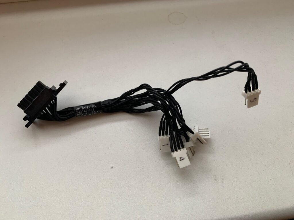
that is in turn connected to the mainboard via its proprietary connector. While I am not a big fan of proprietary solutions, this breakout cable does at least provide a central point to hook up all the fans and allows for connecting up to 6 fans. That is not too shabby.
Fun fact: At full load the 12(!) fans alone could potentially consume
(2×0.35)+(2×0.6)+(2×0.5)+(2×0.35)+(3×0.86)+0.7 = 6.88 A
6.88 A x 12V = 82.56 VA = 82.56 W
As it is now, the two 92mm CPU fans blow the air in a 45°-ish diagonal fashion through the fins of the OEM AIO liquid cooler towards the mainboard and the RAM, creating unwanted air turbulences and therefore making for a not-so-optimal situation. The additional radial fans that blow towards the RAM banks add to the turbulences and prevent an effective directional air flow.
Now, I understand that HP engineers had a clear vision of compartmentalized cooling/air flow. Having the CPU/RAM/VRMs in their separate cooling zone is clever and should indeed be implemented by all OEMs and should be an industry standard by now. The only thing that irritates me is the choice of hardware here, but that is something that would not have bothered me back in the day, but definitely bothers me now.
Instead of 2x 92 mm CPU fans, today I would have chosen 2x 120mm fans in combination with a grotesquely overdimensioned tower cooler, as is standard today. Properly placed, these could make use of the intake air flow from the front and pass the air out through to the back. Increased size of the fans allows for the fans to rotate slower as the 92mm ones while still providing the same (or even better) air flow and lower noise. Cooling down VRMs and RAM banks could be achieved by repurposing the now unused 5.25″ drive bays into one big cooling duct. I think placing one (or two?) 120mm fan(s) that pulls in air at the front of the case could prove to be very effective.
Issues
One could argue that it would be simpler (and much cheaper) to just replace the current fans with aftermarket ones. Well, that would indeed spare me and you lots of work but being overly compatible is not a OEMs primary intention. Unfortunately, it would prove to be partially very difficult to source more quiet replacements for the fans: the radial fans are proprietary OEM solutions and therefore exist no third-party alternatives. And just replacing two 92mm fans just doesn’t cut it.
Luckily, this does not apply to the axial fans. Apart from the plug, which seems to be a MOLEX KK 254 series plug (or some compatible equivalent) these fans seem to be pretty standard regarding dimensions, voltage and pinout and should be replaceable with compatible equivalents.
One notable example are the PSUs fans – here the pinout appears to be reversed. This needs to be further examined:
While google brute forcing investigating this phenomenon, I stumbled across an image titled “Delta DPS-1050DB A_Fan_Pinout.png” hosted on HPs Servers. Unfortunately I was not able to trace that image back to a discussion thread or something similar to get some context. So take this with a rock grain of salt:
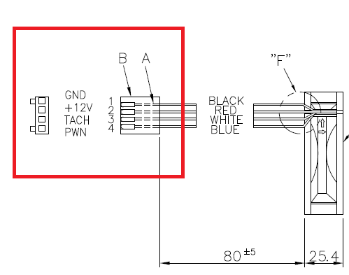
March 10th, 2021
After some googling it was reavealed that – if one may trust the diagram and the associated title – the diagram (DPS-1050DB A) depicts the older z800’s 1100W PSU fan pinouts. Since the manufacturer (Delta) is the same and since the z800 shares many similarities with the z820 anyway, this further strengthens the theory that for the z820s PSUs fans we might just get away by reversing the pin order. We will have to find out by trying it out, eh.
| Pin # | 4 | 3 | 2 | 1 |
| z820 Fan | BLACK | RED | YELLOW | BLUE |
| Typical Fan | PWM | TACH | 12V | GND |
So, my assumption about the PSUs fan pinout must have been somewhat wrong. Trying with either pinout (PWM-TACH-12V-GND and GND-12V-TACH-PWM) yielded a non-booting machine and an error code: the power button lit up in red and the machine beeped 4 times with 1 seconds delays. The manual giveth us knowledge: ‘Power failure (powersupply is overloaded).’
Even though the fans I tried were 0.07A fans, it was too much for the 1125W PSU. This can obviously not the reason for the failure.
So, obviously the PSUs fans must be a special kind of fan. Or have a very unusual pinout. My best guess is that the fans themselves sport some kind of functionality like temperature sensing that cannot be replaced with a standard PWM fan. If you run into the same situation as me, just hook up the original fans and you should be good to go.
I don’t know what to make of this yet, but since these fans weren’t the loudest anyway, I am not going to bother with those now.
The idea
The general idea is to source ‘silent’ fans and CPU coolers that are able to transport 300W TDP combined. Even though I am not planning on putting the machine under any prolonging stress it will be very rewarding should I at one point decide to do so. Therefore i need to find a way to generate a directional air flow through the case. Here I am aiming for a classic front-pull-rear-push configuration. To make the fans work, i need to figure out what the pinouts for the headers are. Here it will be especially interesting if HPs creative 6-pin solution will pose any threats to my endeavours.
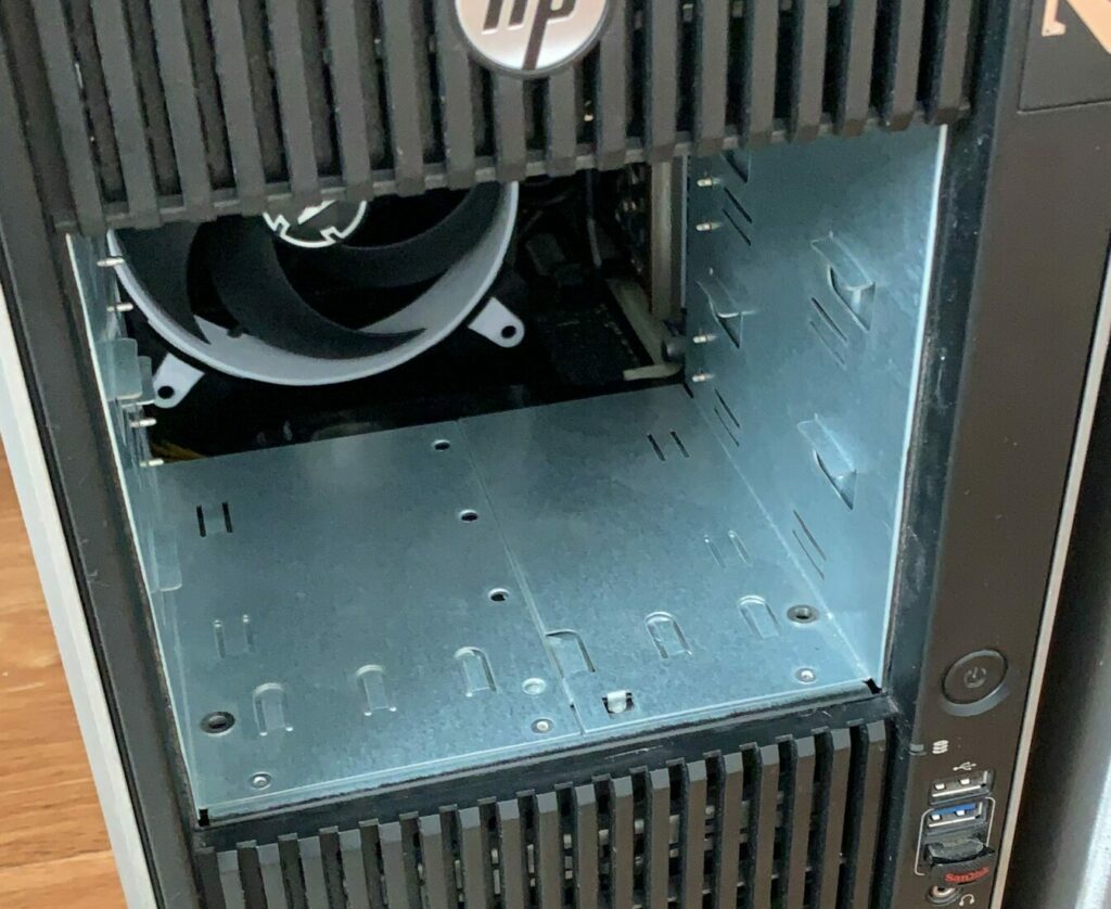
When all that is done, I will have to find a way to get fresh air in through the front. The z820 provides 4x 3.5″ bays and 3x 5.25″ bays for drives and harddisks. Thats all neat, but unfortunately HP did not consider any intake fans at the front and therefore did not leave any space for them. I am pretty positive that I will be getting rid of all 5.25″ drives so that may free up some space to get creative. Apart from getting some space for the fans, I will have to think of a way to get fresh air in through the front without having a gaping hole where once the drives were.
Lastly, I will have to think about cooling VRMs and RAM banks, these can get pretty toasty under prolonging stress.
TL;DR:
- source a replacement for the subpar HP AIO cooler (✔)
- source 120mm, 92mm and 80mm fans (✔)
- research pinouts (✔)
- ponder about how to deal with the 6-pin contraption of the rear fans (✔)
- construct a 5.25″ drive cover visually complementing the rest of the z820’s front (✔)
- ponder about how to get air flow to VRM and RAM banks (✔)
- write it all up into something someone might want to read (✘)
The process
After some testing with an expendable fan that I had laying around, it became clear that the plugs HP uses to connect the fans to the fan headers on the fan bracket and the mainboard (with notable exception of the 6-pin exotic) are just different from industry standards because of reasons™. Apparently, HP does not want you to buy cheap, reliable and efficient aftermarket fans that you can just plug in on your own.
Instead, HP wants you to buy cheap, reliable and efficient aftermarket fans where you just have to cut off one of the plugs posts and then plug in:
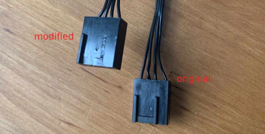
The different plug layout just seems to exist to disencourage brave people like yourselves from using cheap aftermarket components.
Apart from a small physical modification there are no additional requirements to make the fans work. Just be careful to honor the correct voltage (12V DC) and the maximum current as per the original fans installed.
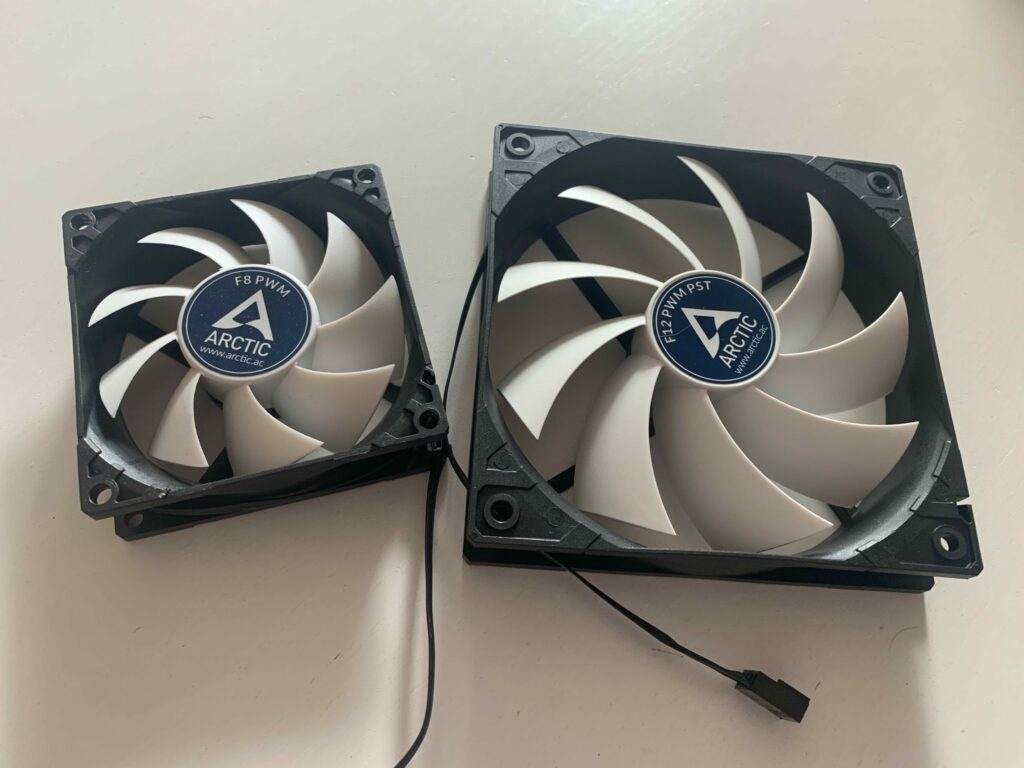
As to my choice of case fans, I went with the typical 80%-approach. I wanted to have quiet, somewhat-quality budget-friendly fans. After some research, I went with Arctic’s lineup of fans, namely the 80mm, 92mm and 120mm versions of their F-Series. Not only did my research conclude that these were the best choice for me, but also my experience. In earlier projects I already used Arctic PWM fans, and was always pleased with their performance.
All in all I got:
2x 80mm Arctic F8 PWM (rated max. 0.09A)
4x 92mm: Arctic F9 PWM (rated max. 0.09A)
2x 120mm Arctic F12 PWM (rated max. 0.12A)
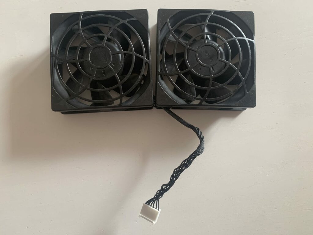
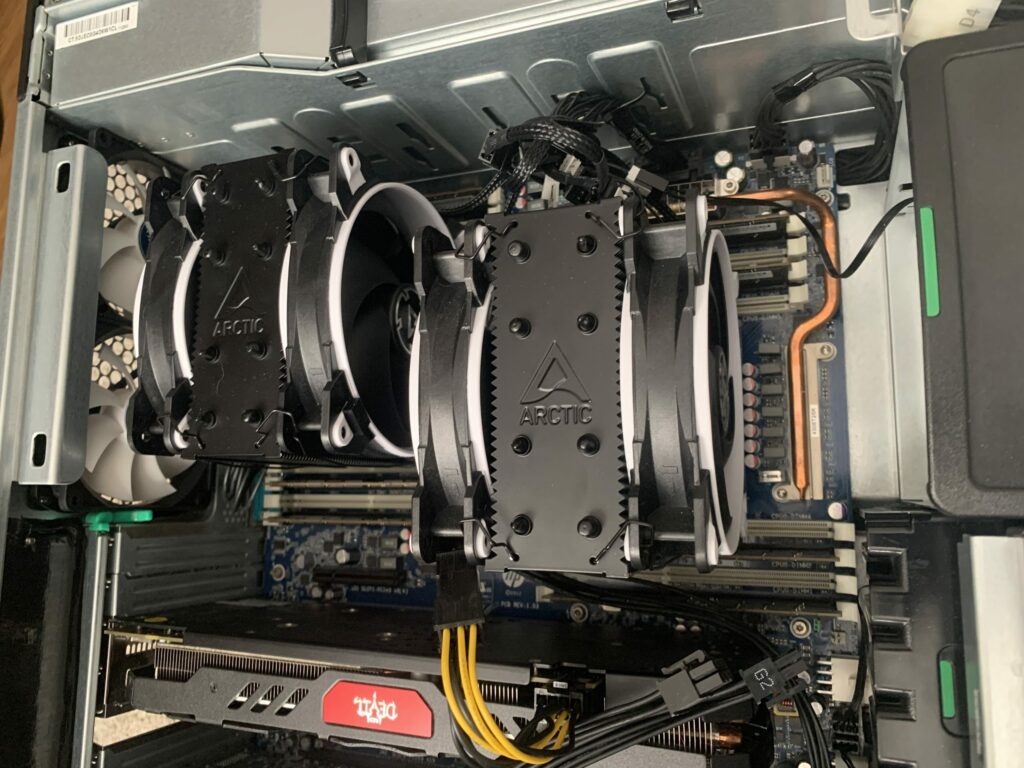
Regarding new CPU coolers, I decided to go with 2x Arctic Freezer 34 esports Duo. There may be coolers out there with better thermal performance, but I am pretty confident that, in light of better air flow within the case, these will be just fine and capable enough of transporting the heat.
Apart from that, these coolers just fit the geometric constraints of surrounding components such as memory banks, as well as the limits of the case itself. It just so happens that the coolers just barely reach the side panel of the case. Regarding width, they pretty much use up all the available space, without compromising too much serviceability. Both coolers come with two 120mm silent fans, promising to cool these Xeon beasts without becoming too noisy or hot. One pretty neat thing about the ‘Duo’ variant of the cooler is the fact that both fans are connected to the fan header using a single plug. This is achieved by first plugging one of the fans into the receiving female connector of the other. So, while having two fans hooked up, you just need one fan header on the mainboard to supply both.
The 6-pin drama
Yes, well, the elephant in the room. HP decided to create something special, something truly unique to behold. You see, except for the rear case fans, HP just used slightly different plugs for case and CPU fans. So far so good. Not for the rear though. The rear is special. So special in fact, they had to come up with something that befits the occasion. So HP designed this beauty:
So, instead of just having two separate connectors (like with the hdd bay fans) HP opted to go for a combined 6 pin connector. While researching the pinout I came across the z800’s connector pins page. Thankfully, HPs z800 and z820 designs are pretty similar, so I assume that the pinout will be the same for the z820.
Section “Workstation rear system fans, P8” states for the pinout order:
| Pin # | 6 | 5 | 4 | 3 | 2 | 1 |
| Signal | PWM2 | TACH2 | PWM1 | TACH1 | +12V | GND |
When looking at the cabling, it becomes clear that HP just took two regular PWM fans, soldered each +12V and GND together and stuck them in this non-common plug. That’s it. Thanks, HP.
In order to work non-destructive, I will demonstrate how to create a compatible plug on your own. I did not reuse the original one, simply because I was too lazy to record the assignment of the black, otherwise nondescript cables. You know, just in case to be able to use the original one as backup.
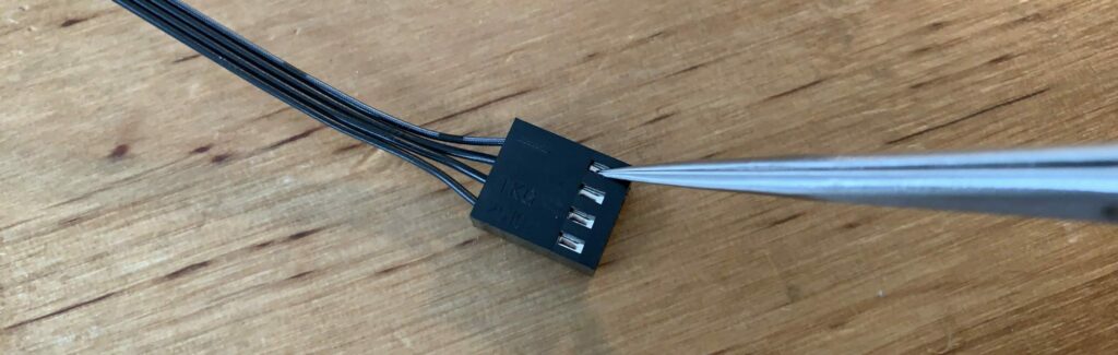
What I did to overcome this obstacle is the following:
I took two regular Arctic F9 PWM fans, and removed the contacts from their plugs. To do that, you just have to look at the plug from the back side. Grab something pointy – pliers or a small knife will do – and push one of the silver contacts while gently tugging the corresponding cable to remove it. Do not apply excessive force!
Once you have done that for both fans, you need to create a new plug for the cables to be plugged into.
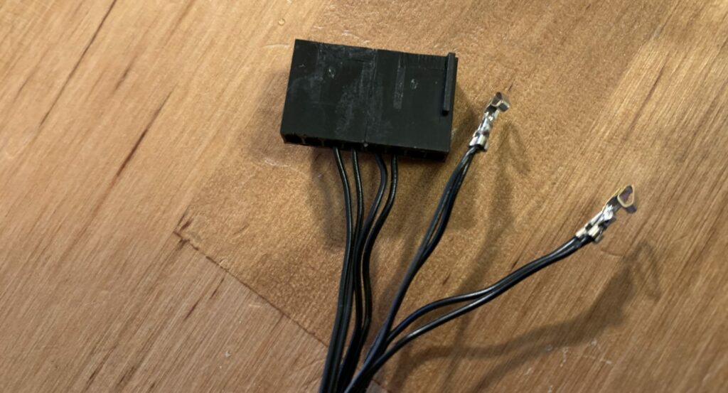
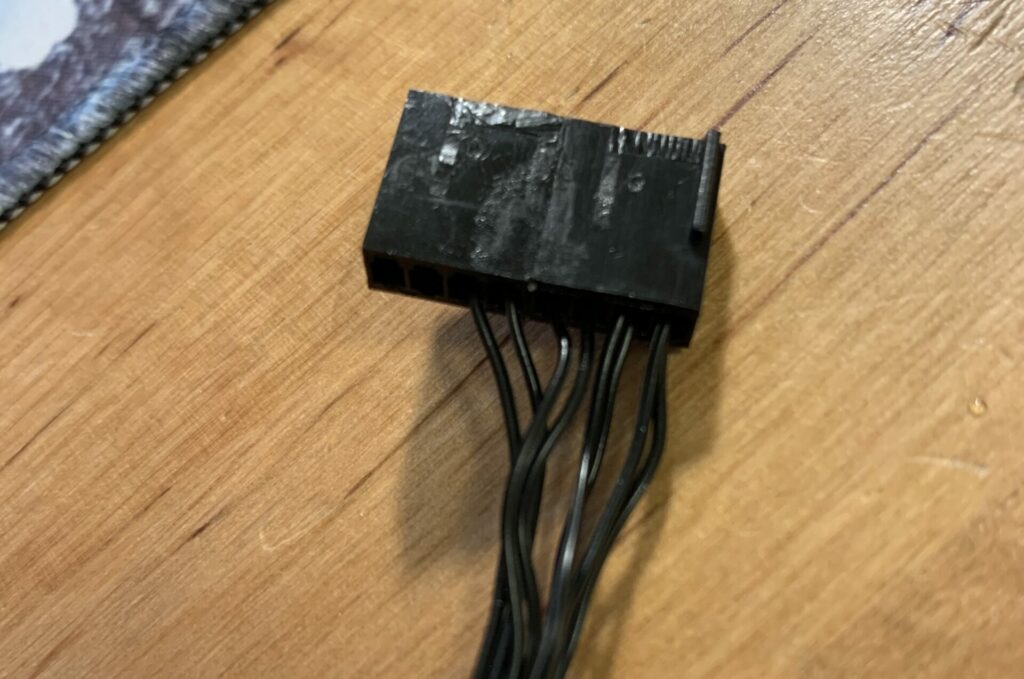
To do this, I just reused the fans’ plugs that I removed the cables from. I cut away the superficial posts, gently sanded the sides of the plugs and glued them together using super glue:
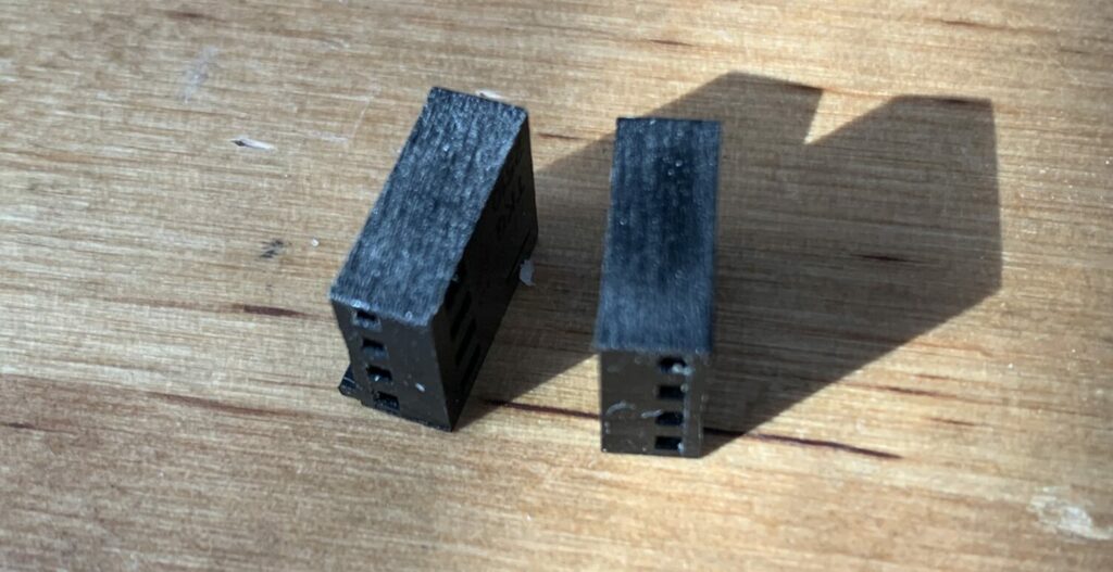
You surely will have noticed that I now have a plug with 8 instead of 6 ports, and we all know, more is always better! Jokes aside, I was just way too lazy to cut off 2 unnecessary ports – you can do that, but it won’t hurt to leave them as is – they won’t collide with any modules on the board.
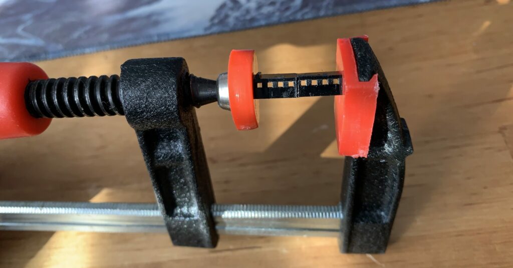
Next, I combined 12V and GND cables of both fans simply by cutting off the contacts on one fan and soldering the castrated cables to the contacts of the other. Do not cut off the PWM and TACH contacts!
All thats left to do is to plug in all the contacts in their respective order. Do not mess this up as this can possibly cause some damage to the fans and/or the mainboard.
This is the finished product:
Well, all that’s left to do now is to replace all original fans with the new ones. Mounting the new CPU coolers was pretty easy, all you have to do is follow the instructions on Arctic’s website.
I will not demonstrate how to do that, since at this point I will just assume that you possess basic computer building knowledge.
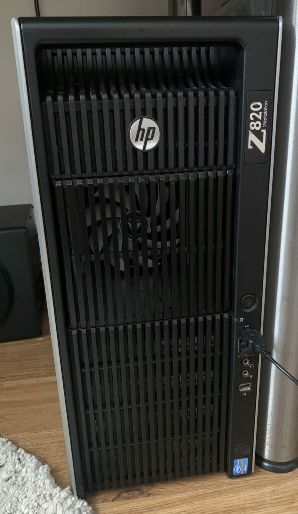
A few images of the result:
Having swapped out almost everything cooling-related in this case, we still have to do one last thing. In order for this all to work, we need proper airflow directed through the case. When the design of the workstation was conceived, we all still had one or more optical drives in our computers, preventing an efficient, direct front air intake. Nowadays, we don’t. So why don’t we use the unused space for a solution to the air flow problem?
My solution is as follows: Using FreeCAD, I constructed a 120mm fan mount (*.stl at the end of the article) that clips right into the pins that are supposed to hold 5.25″ drives in place:
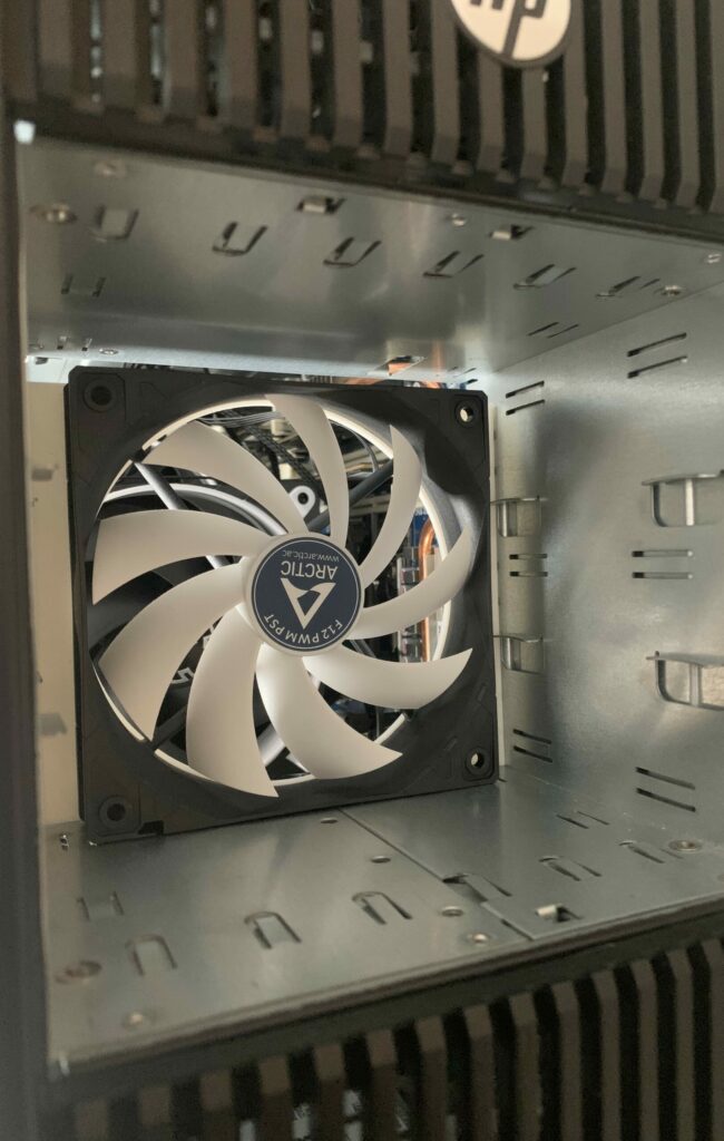
Just hook up the 120mm fan to one of the fan headers of the proprietary fan bracket, and you are good to go.
Unfortunately, this solution prevents us from using the drive boxes/front covers, leaving us with an unsightly hole in the front:
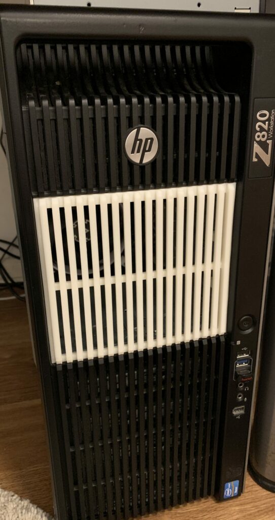
Making it pretty again
Having nightmares about this orifice in my beloved z820, I decided to design a visually complementing cover/panel to create a neat front surface, again using FreeCAD (*.stl download at the end of the article). It solves two problems: It closes the case and provides a visually pleasing end to this nightmare of a supposedly simple upgrade and second, it still allows for sufficient air flow through the front. I 3D printed the part with my Creality CR10S printer and sprayed it RAL 9005 matt black using “The Army Painter”.
The cover simply clips into the pockets left and right of the hole:
One more thing…
While testing my new setup I was able to confirm that the machine as a whole has already become significantly quieter, mostly because the new fans are designed more towards low noise level and high efficiency rather than longevity and performance. Since I keep tabs on my hardware on a regular basis, this should not become an issue at all.
Due to the reduced noise level I quickly identified the last noisy culprit in my system: HP decided to disregard any fan control for the rear fans and just powers them 12V, full PWM all the time. Trying to rule out any fault by myself, I hooked up the original 6-pin fan construct with no change in behavior. My assumption therefore is that HP just flat out decided to drive the rear fans with max RPM to create some amount of negative pressure within the case. This makes sense, since it did not have any intake fans directly at the front or somewhere else.
Due to my improved setup, it is just not necessary anymore for this kind of aggressive fan behavior. Since HP does not allow to control individual fans using fan curves in BIOS/EFI or through software, I had to come up with a different solution.
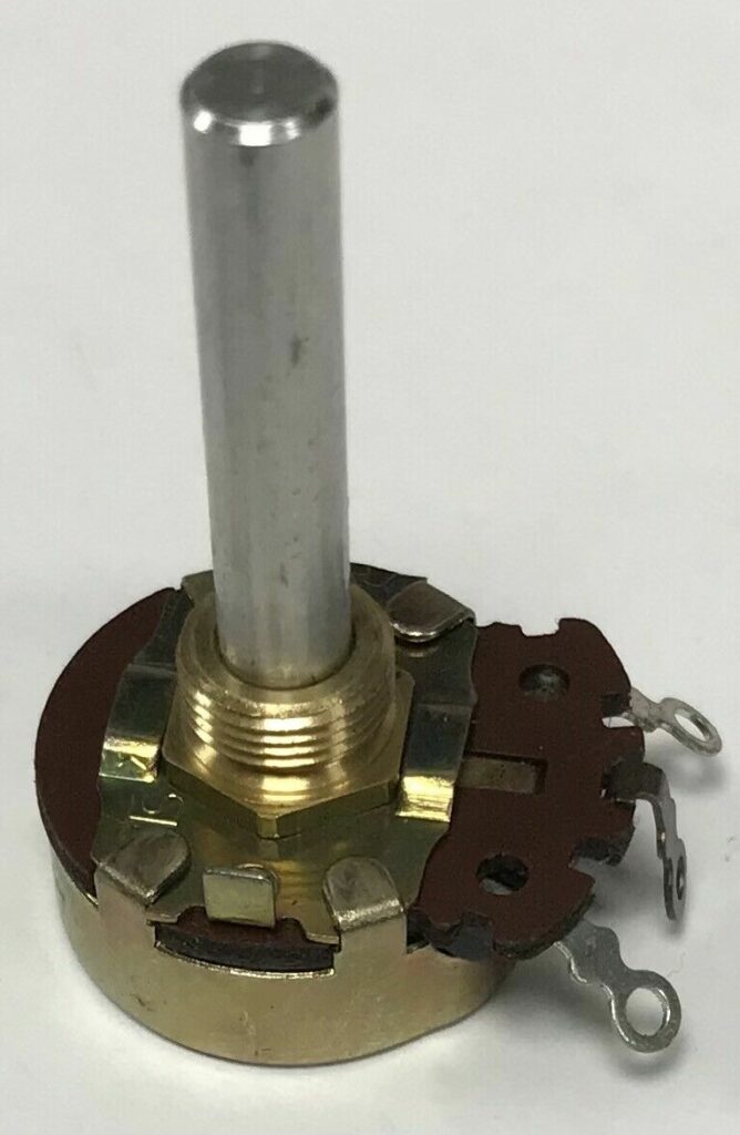
Back in the day, when fan controllers were either non-existent or outrageously expensive, humble pc builders like myself used potentiometers to control the voltage supplied to the fan through variable resistance. Increased resistance means less voltage means slower fans.
This was also encouraged by the fact that PWM fans where either similarly expensive or just not supported by the mainboard.
Feeling 13 again, I went on to calculate the requirements of the potentiometer I was going to use. Since both fans were hooked up in parallel, I had to deal with a rating (maximum heat dissipation) of
P = (0.09A * 2) * 12V
  = 2.16 VA
  = 2.16 W
To have some dynamic range in controlling the fan, I decided to step down the voltage to a minimum of 5V. This allows to reduce the fans speed so much as for them to even come to a halt.
This means a reduction of the voltage by 7V. Some quick math:
The basis of all calculations is Ohm’s Law.
Resistance of the fans themselves:
V = I*R ; Ohm's law, therefore
R = V/I ; therefore
R = 12V/(0.09A*2)
R = ~66.6Ω
Since we are targeting a minimum of 5V, we must calculate the target current at 5V first:
V = I*R ; Ohm's law, therefore
I = V/R ; therefore
I = 5V/66.6Ω
I = ~0.075A
Now we need to set the voltage drop in relation to the minimum current to get the required maximum resistance of the potentiometer:
V = I*R =>
R = V/I =>
R = 7V/0.075A
R = ~93.3Ω => round
R = ~100Ω
So now we know, that in order to step down the Voltage by 7V, we need a potentiometer that is capable of dissipating 2.16W of power and that its resistance must be configurable between 0Ω and 100Ω.
A quick search on eBay returned a plethora of results. The one I decided to go with is rated for 4W and 150Ω, so that leaves me with a bit of headroom.
The potentiometer arrived after a few days and I went straight ahead and soldered the whole thing together.
Here is a simple circuit diagram of how everything gets connected:
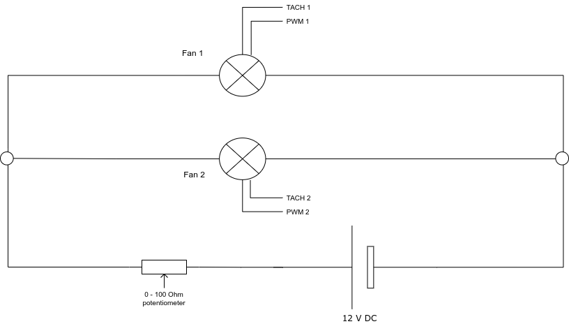
Please refer to table 2 for the pinout of the mainboards header.
Here you can see the result, already glued into position:
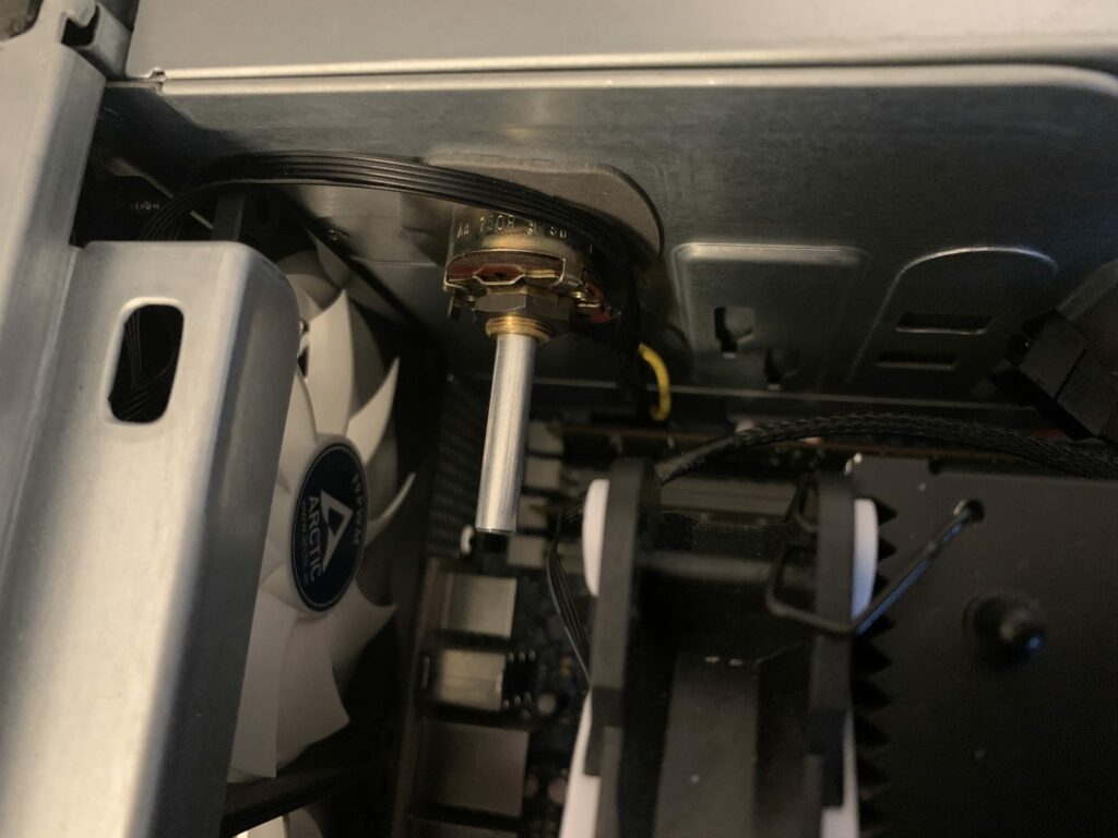
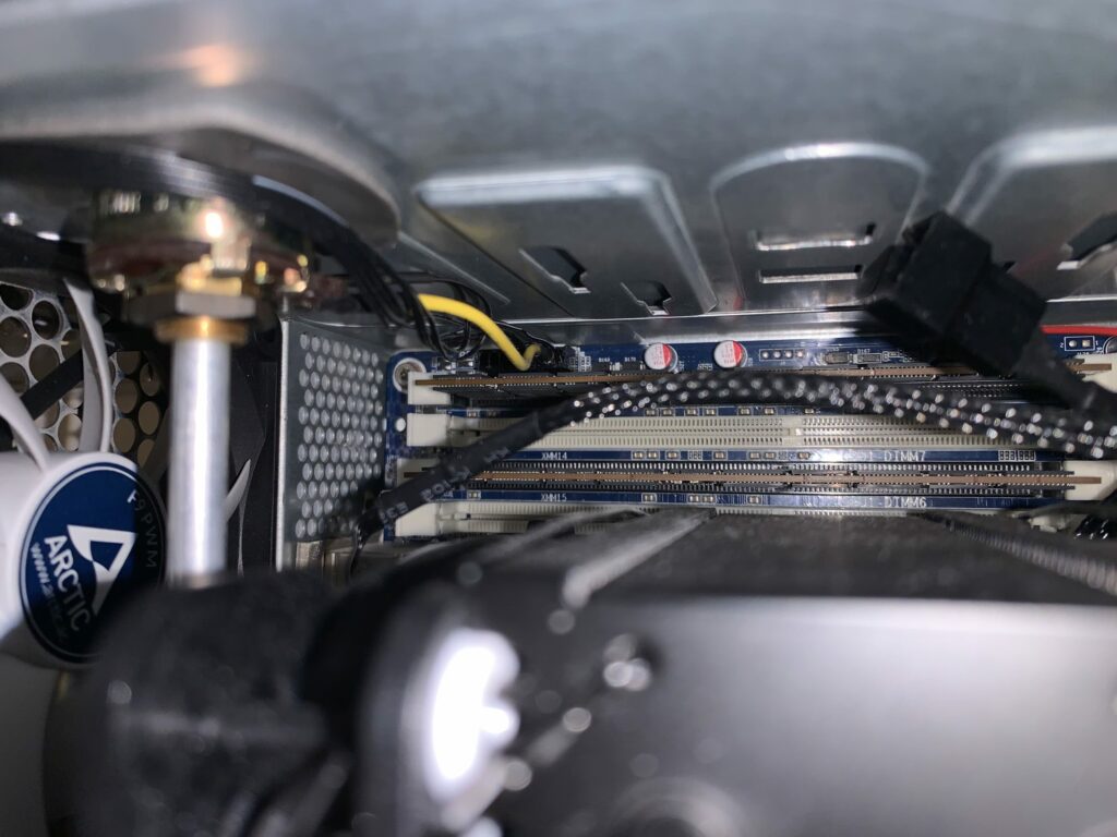
After booting up the machine, i just had to fine tune the resistance using the potentiometers’ knob to something suitable for my use case. Now the rear fans run very quiet but still push lots of air through the rear exhaust. When it gets hotter during summer I will maybe just have to adjust it once to have a little more air moved through the case to compensate for increased ambient temperatures.
One last more thing… the “Press F1 to continue” disaster
Now the last thing that is bugging me is the fact that HP decided to hard code a system halt routine into the firmware that fires when not all fans are present and/or running. I feel this is very pushy, as one can not permanently disable that safety measure. So every time one boots the machine, you have to press F1 to continue the boot process.
To bypass this, I first thought of installing a few additional fans inside the machine. But looking at the already pretty satisfying performance of my custom cooling setup, this seemed unnecessary to me.
So if I am not going to install real fans, why not fake some? To do this, I would have to make the firmware believe that there is a fan running on the unused fan headers.
After some research, I came across NE555 PWM signal generators. These very compact generators create a PWM signal that can be adjusted, too. Many come with voltage converters and therefore can run off of 12V, so you can power them directly off of a fan headers +12V DC source. The PWM signal will then be used to fake running fans by sending it to all the unused TACH pins.
This is the assembly I am using:
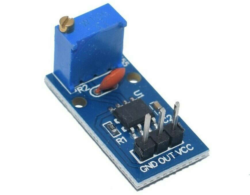
If you happen to own one that runs off of 12V, just connect GND and VCC to an unused fan headers corresponding pins and then connect the OUT pin to the TACH pins of all of the unused fan headers. Just make sure that you do a proper soldering job so you don’t short/destroy anything.
And there you have it. My machine is now running much quieter, no gurgling from the liquid cooling pump, the thermal performance is measurably better, no water cooling failure possible anymore and it is easier to service, all in all. My CPUs are idling at ~30°C (86°F) and ~32°C (90°F, ambient room temperature of 20°C, 68° F) at the minimum fan speed setting. Under prolonging synthetic load on all cores the temperatures never rise above 63°C (145°F), thermal throttling never becomes an issue.
UPDATE: Now that it is summer in Germany I once again took a close look at the temperatures. Nothing changed that much. Ambient room temperature has risen to 25° C (77° F), idle temperatures have risen to 33°C and 35°C (91°F and 95°F respectively), synthetic prolonging loads result in temperatures rising to about 68°C – which is still not a concern since Intel specifies a maximum TCASE-Temperature of 72°C and I won’t be running synthetic loads over a long time anyway. And if I do run some memory/CPU-intense workloads, these get load balanced anyway and never stress the CPU that much. So nothing to worry about. CPUs never stop single-core turboing to 3.95 GHz, all-core turbo of 3.6 GHz never gets throttled.
Mission accomplished, I’d say.
Citation: me
Tags: HP, z820, workstation, modding, fans, temperature, quiet, pinout, noise, loud
—
These sources helped me a lot and might be of interest to you, too:
http://voodai.blogspot.com/2017/01/hp-z820-workstation-fan-inventory.html
https://support.hp.com/us-en/document/c01718096
z820 QuickSpecs: https://www8.hp.com/h20195/v2/getpdf.aspx/c04111526.pdf
z820 Maintenance and Service Guide: http://h10032.www1.hp.com/ctg/Manual/c04205252
z800 Connector Pins: https://support.hp.com/us-en/document/c01718096
Downloads

License: Creative Commons – Attribution Non Commercial Share Alike 4.0 (CC BY-NC-SA 4.0)
O boy…this is my problem right now – I got 2×3060 ad they are much to big for dual GPU order – they are heating-up each other, right now one of them are in riser outside case…
I’m thinking about rebuilding original case, with customizing-assembling CPU watercooler with direct fan – and Yours post shows me that it possible, or making a quasi-custom plywood-aluminium rig with free air, but there still will be problem with BIOS warring about fans, so may some dummies ? Need to think, design and try, but thanks a lot for this post!
Hey Greg,
in a few days time I will be updating the post to reflect the additions and changes that I have made in the past few weeks. For instance, I have added a simple PWM signal generator that fakes running fans for the now unused fan headers. Stay tuned so you dont miss out, it may be relevant to your own project!
Great guide! Thanks!
Did you solve PSU fans quest?
It seems, there are 80mm high RPM (around 4000-4500 rpm max), high CFM (~50) PWM fans with RPM sensor and standart pinout.
Probably, there some kind of startup RPM chech, system couldn’t reach that 4000rpm and stating failure 🤷
Any ideas about not so noisy fans for replacement?
Hello Evgeny, thank you for your comment. Unfortunately I did not have the time to source compatible, quiet psu fans yet. But I will do that, eventually. I don’t know what the reason for the startup failure is, yet, but I will continue to investigate – your ideas provide excellent starting points. As for high CFM low noise fans, sadly I can not help you out. I am sure that a quick search on https://geizhals.eu/?cat=coolfan can at least provide you with the information you seek.
Thanks!
What I found to this moment: according to ADDA AD0812UB-A7BGL datasheet (this fans appear in some units), this fans have protective circuit by transistor with speed sensor. So it’s a good clue.
Hope, it could help. Please, feel free to email me with any questions.
By the way, you can delete my doubled message above)
That’s an excellent find, thank you! I will investigate further and update the post once I find some time.
Dear Claudio,
I’m really appreciate for your tutorial. You helped a lot!
Just finished with mine, and it’s sooo good 😌
By the way, I’ve followed ‘BeQuiet’ path instead of ‘Arctic’, but main steps are the same.
Here’s some update:
You were right, there’s non-standart pinout in PSU fans, so just follow this colour guide and you’ll be good
https://landing.coolermaster.com/faq/3-pin-and-4-pin-fan-wire-diagrams/
I’ve installed a pair of used Cooler Master Blade Master 80 (3000rpm), and they work fine. It’s noticeable quiter now, but there is still slight high pitch mechanical whine. I’m not sure, is it normal for them, or it just because they were used, so I’ll try something else.
Wish you the best!
Hi Claudio
Thank you for this amazing guide!
I recently acquired a Z820 with a broken CPU cooler from work, I took it home as a little science project for my son and I to work on. initially I looked into getting a new CPU cooler but then stumbled upon this page and now have decided to follow your excellent modifications instead.
I have decided to use the mutliple fan headers (from the cable which used to feed the enormous CPU cooling contraption) for the 2 rear fans, rather than making the custom 6 pin plug as you have done. Do you think that would work? Also do you think that would then make the potentiometer redundant?
Many thanks again
Nick
Hey Nick, boot – which can become very annoying.
if you have fan headers left on your fan splitter at the end of your modifications you can use those of course. Just keep in mind that if you leave any of the fan headers unused (be it on the fan splitter or the mainboard) the BIOS will complain and prompt you to press F1 on
Many thanks again Claudio for your guide. The machine is up and running, and is now much quieter! I did use the multiple fan splitter cable to feed the rear fans which also allows me to control them in the BIOS. I do have to press F1 to boot currently, but will probably do the PWM signal generator mod next.
Really helpful, especially with the 3D models for the fan bracket and front cover, so again, thank you very much!
Cheers
Nick
Nick, you are very welcome! I hope you and your son enjoy working on this versatile machine as much as I did! I am planning to hook up a usb fan controller to the fans in order to control them individually and automatically from within the OS; I will be updating this guide when I am done – maybe thats an interesting upgrade for you too?
Hi Claudio, thanks for your interesting guide! I`m in the same position to change the coolers at the HP Z820, started with the PSU. Bad mistake, same problems as you wrote. But what happend then with your PSU, is it still broken ? You did not mentioned, any trick to get it alife again ? It seems, that PWM and Tacho are rotated at the PSU plugs?
Nice regards
Hi Dominik, unfortunately I have not yet found a way to replace the PSU’s fans. The problem seems to be that the original fans have some sort of functionality that any replacement fan does not. My guess is that it must be some sort of thermal sensor. I reconnected the original fans and the PSU started working perfectly again, I suggest you do the same – these weren’t the loudest fans in the system anyway. Regards, Claudio
I modified my Z800 with Noctua fans. Your article really helped.
What is the pinout/connection for the Chassis(rear fans) the 6 pins and the potentiometer? I could not see in the image.
My Setup:
– Z800 CPU fans replaced with CPU fans Noctua NF-B9 Redux 1600 PWN and bridged pin 1GND and Pin 5 on motherboard
– on frontpanel fans I added Noctua NA-SRC7 low noise adapters(will change for potentiometer as well)
I did not know the rear fans and front fans are running always full speed. First thought was the ambient temp sensor was broken, I replaced (NPN 2N2222 transistor) and checked. but it is fine. (When broken or loose BIOS is showing 0 for ambient temp)
Also I bought some sound isolation foam for the case, I removed the plastic cover in the middle, because the Noctua heatsinks are to big.
Hope you can show the connetion for the potentiometer and the rear fans, thanks!
Hello Bob, thank you for your post!
You can find the pinout for the rear chassis fans in the section “The 6-pin drama”. Please note that these are only valid for a z820 workstation, but they might be the same for the z800.
Your are right, I did not clarify how I hooked up the potentiometer to the rear chassis fans, I will correct that in an update to this post in a few days.
Hi Bob, by popular request I have added a simple wiring diagram to the article. Regards, Claudio
Hi Claudio, i just read your post.
I have a Z800 dual cpu in wich i replaced the CPU air cooling into the official liquid cooling kit from hp.
The thing is that the original fans on the exit are used to cool the lc radiator on the back.
As you wrote the are at full power.
So it’s still (unnecessary) noisy.
Since i use my z800 as a digital audio workstation silence is a must.
I hope that with your guide i can silence my Z800. Because even for it’s age it is a decent working horse. Just that noise is irritating me.
Hello Sven, thank you for your input. I do not know the specifics of the z800, but I am confident that it shares many of the z820’s characteristics, so let me try to put your expectations into perspective 🙂 My machine has top of the line CPUs with thermal envelopes of combined 300W, ignoring chipset, memory, gpu(s), drives… and that heat has to go somehow. Even if your machine has different, less power hungry components, I still think it will prove to be a challenge to get it as quiet as a sound engineer requires it to be. If you find ways to get it really – and I mean really – quiet please share them with us!
Hi Claudio,
I have 2 xeon W5590 inside the Z800 (https://ark.intel.com/content/www/us/en/ark/products/41643/intel-xeon-processor-w5590-8m-cache-3-33-ghz-6-40-gts-intel-qpi.html)
TDP per CPU is 130W, so 260W combined.
Good thing about the liquid cooled radiator is that it is actually outside of the case on the rear.
See figure 3 on https://support.hp.com/us-en/document/c01829154
Another thing i should consider is that with the liquid cooling the exhaust fans become ‘part of the cpu fans’ check the wiring of the exhaust/radiator fans in figure 18 here:
https://support.hp.com/us-en/document/c01829154
That wiring splits of of the cpu fan connector, 1 side connects to the luiquid cooled heatsink, the other cable goes towards the exhaust fan but in the middle of that cable there is a small pcb (wrapped in plastic foil) where the cable combines with the exact same configuration from cpu fan controller 2. (damn this is hard to explain)
I guess that pcb does ‘something’ to the fan control signal or even it has a sensor of some kind on it or so (it is not clear what it exactly does)
So theoretically by replacing the standard hp exhaust fans with relatively slow turning, low noise exhaust fans (those cool the radiator/blow air over the radiator) i think i can get the system a lot more silent.
Since the radiator don’t need a big airflow to cool off (large surface and it is outside the case) i think a slow turning fan 2 actually) could do the job and keep the inside cool enough of the case.
(i could try to replace the front case fan too by a low noise fan, or put 2 slow turning front case fans instead of the 1 stock front fan for further noise reduction)
Ps. I’m not a professional sound engineer, i’m an amateur with a big passion for music production, and a small budget 😅
This is also the reason i use a 12 year old hp Z800 i bought 2nd hand for 500 euro 5 years ago 😊
My payed job is IT sysadmin.
I think I get the situation now. Telling from the images, both the (2) rear exhaust fans as well as the (2) ‘Asetek’-type pumps in the CPU cold plates get powered and controlled by only two headers on the mainboard. While the pumps get their power and signal directly from the motherboard, the headers also provide power and signal to the mystery pcb you mentioned where both get combined somehow. From the images, I can only identify 4 colored cables that go from the pcb to the rear exhaust fans, can you confirm that? If that is the case, then consequentally they must be split again for both exhaust fans to provide each with 12V, GND, Tach and PWM.
Hello I have a z840 and I was considering getting a vapor cooler and leaving them unplugged so the bios wont change the fan curve. I dont mind the sound just want the cooler temps. Has anyone used the Vapor Z coolers in this configuration. Im curios to know the temps compared to using a after market cooler set up.
http://www.hp.com/global/hpinfo/newsroom/HPZWorkstation2015/HPZCoolerforHPZ840WorkstationDatasheet.pdf
UserBenchmarks: Game 109%, Desk 85%, Work 99%
CPU: Intel Xeon E5-2643 v3 – 79%
GPU: Nvidia GeForce RTX 3060 Ti – 134%
SSD: Samsung MZFLW1T0HMLH-000MV 1TB – 158.9%
SSD: Crucial M500 480GB – 86.6%
HDD: Seagate ST310004CLAR1000 1TB – 49.4%
HDD: Seagate ST310004CLAR1000 1TB – 55.2%
RAM: HMA451R7AFR8N-TF 32GB – 117.8%
MBD: HP Z840 Workstation
Hi John, unfortunately I have no experience whatsoever regarding this cooler. The solution is interesting as it eliminates the possibility of a failing water pump in HPs water cooler while seemingly providing sufficient cooling. There are quite a few videos on youtube demonstrating the performance:
https://www.youtube.com/results?search_query=hp+z+cooler
Give us the pinout for the 6pins chassis (rear) fans and the potmeter, pleaseeee
Hello Mosa, by popular request I have added a simple wiring diagram to the article. Regards, Claudio
I have a Z840 and am using the optical bay drives as additional HHD drive bays using an ICY Dock 3x HDD converter, which limits the option to add an intake fan in that location. Any other ideas on how to improve intake airflow while still using the optical bay drives for additional HDDs? Thank you.
Hi Claudio,
great website! Love your work!
We also have the same cooling failures with several Z400 and, recently, also with Z820s. I already converted these machines to air cooling, however, the F1 issue is still unsolved (and very annoying).
Did you do your own PWM pcbs? Or are there any ready boards available on the net?
Thank you, Hannes
Hello Hannes, these PWM signal generators can be bought cheaply off eBay. Just search for “NE555”, you should be able to find pcbs that are very similar to the one described in the article for around 4€. Greetings, Claudio
Where can I download STL files for inateka FAN’s and the cover for the hole in front of the case?
Hello Julius, the download links are at the end of the article.
Hey so, I solved the problem of replacing the fans in the power supply.
I installed some Noctua Redux 80mm fans in my PSU, and like you had the problem with the machine turning back off as soon as it was powered on.
Turns out that the fans inside the PSU are not PWM, but are actually voltage-controlled 4-pin fans. There is an article on Noctua’s website which explains this:
https://noctua.at/en/how-can-i-check-if-my-4-pin-fan-header-supports-pwm
Seeing that there was two V+ supplies feeding the fan on this type of connector made me realize the PSU was probably detecting a short and shutting itself off. I took apart the connector, removed the fourth pin from its socket, and re-assembled the PSU and Z820.
Hit the power button, and it turned right on.
Hello,
thanks for the tutorial, I was able to drastically lower the temperatures on my z820, the old liquid cooling units were pretty much done with me.
As for the F1 drama, I took the tach pin of a fan and put it on all unused headers. this also works fine and saves you the 555 timer.
Hello Fiete, happy to hear that! Your approach sounds much more elegant than my solution, I have no idea why I never thought of that. I will update my post with your solution as an alternative. Thanks for sharing! – Claudio
I own an HP840 and at some other point I owned an HP820. The HP820 is much noisier workstation than the HP840. But even if quieter, the HP840 is noisy specially in a quiet environment (or at night). Even with the HP 3D vapor coolers which I had installed and was using.
I believe the HP 3D vapor coolers actually kept the fans from spinning faster under significant workloads and contributed little to reducing the base noise the fan system made.
So I made the changes outlined in this posts and this computer ( the HP840 I have) is quieter in general and the noise the fans emit and is more pleasant and neutral.
Thanks for your research and experimentation and for sharing!
Juan H.
This is an impressive hack! This is something I have never thought of before and the final solution you implemented is quite beautiful in fact. I installed dual HP Z-coolers after the factory water coolers began to die and leak. Z coolers are extremely effective, my Z820 runs quiet most of the time now, except under rare heavy load the fans will speed up. I hacked my Z820 to install three GPUs.
https://www.facebook.com/media/set/?set=a.2324347777600160&type=3
Just wondered if people reading this know you can set the minimum duty cycle in the bios to 1 (or 0 if brave), reducing fan noise considerably
I have two z820’s one is quietish with the minimum duty cycle on 2/6 in the bios. The other has 2 ram blower fans that sound terrible on the same setting, which can be ordered from aliexpress for £11 each
I would recommend checking/setting the bios setting before these modifications, and consider brands other than arctic to meet the cooling specifications of the systems fans in CFM, Foxconn for example have compatible fans. It has been rare for the CPU assembly to get hot without the AIW demanded CPU’s in the systems I have. E5-2667 v2’s peak at 66 degrees for a thea render workload, furmark cpu stress test, and other tests. Maybe a marginally more efficient CPU would solve excess heat issues if you have one of these ****w cpu’s, I don’t think they are really optimal, nor do I think they offer much over the next option down.
Thank you for your input! Although not explicitly mentioned in the post, I had set the fans duty cycle (“thermal”) to minimum but was not satisfied with the result. And considering the choice of fans and following this article in general, it should go without saying that you yourself, dear reader, should consider carefully wether or not to follow my humble suggestions (and which, of course). This is nothing but my non-expert solution to a perceived problem and even if one is not following through with every step along the guide, it might at least be a starting point. I wish you all the best for your project!
Hello Claudio, I just wanted to comment on the problem the rear fan runs at full speed all the time.
Just because the solution is so ridiculous.
I was quite sure mine did not in the first place but eventually I had the same problem. I installed HP performance advisor and realized all fans were running at elevated speeds. I did some research and found quite a few people obviously having this problem and some “solutions” that do not work.
It has /nothing/ to do with the ambient temps and nothing with the hw configuration.
It is a firmware bug, if you ask me and there is a simple solution. If you turn on SATA RAID in the firmware instead if AHCI the fan speed does not ramp up after POST anymore. It seems when you run AHCI mode the firmware is missing a step in the boot process and does not slow down the fans or whatever- well, actually it ramps them up after post when in AHCI mode but only god knows why! Actually they don’t run at “full” speed but at rather high speed… rear fan 2000k rpm and front fan 1300rpm.
I hope that this helps anyone desperately searching for the root cause like me and save some hour of their lives!
Hello Zacha, Thank you for your valuable input! Oh I wish I had known sooner, it would have saved me a lot of time… this has the potential of ridding the project of the janky solution with the potentiometer. Thanks for letting us all know!
Do you have a solution for getting the fan speeds shown with lm-sensors? I have now used a 50ohm resistor (from a noctua silent adapter) with the original rear fans which gets the z820 reasonably silent. I would like to monitor fan speed though….
Hi Zacha, unfortunately the sensors are not accessible through an OS, at least my research did not show any means to achieve that. If they were accessible, we would probably not have to tune the fans on an electrical level – which would be very cool though.
Wow, you are so serious and dedicated, two thumbs up. I bought several days ago Z840 and have the same dilemma, in the shroud already disconnected 4 memory fans and left just 2x CPU fans. So I’m getting 4 memory fan that aren’t present and requires Enter to continue booting. Tried to copy for 4 memory fans to the Motherboard way 2 signal pulses (pin 1 and 2 -yellow and blue) from the front fans but it’s not working as once worked for Dell server. I wonder what HP does extra to detect no physical presence? So the workstation either don’t detect any change and the same 4 errors or I had PSU red alert, weird? Any ideas. Many thanks and again I admire your seriosity and so much dedication to your workstation, very remarkable nowadays.
Hello Albert, thank you for your feedback and your acknowledgement! It was a fun project for me at the time, but since energy prices have surged in Germany, I was simply not willing to pay for it anymore, even though I still believe that these are incredible machines. Unfortunately I never had the pleasure to play around with a Z840 but I think HP has implemented a few new shenanigans to obstruct your path to cooling greatness. I wish you all the luck in circumventing these artificial barriers! -C
This is an absolute lifesaver! My Z820 was a noisy beast, but thanks to your expert advice, it’s now running cool and quiet. The detailed instructions and tips were incredibly helpful. I can’t believe the difference! Thank you so much for sharing your knowledge and experience. You’ve made my workstation a much more pleasant place to work.
I’m glad I could help someone! These things are still going strong in ’25, but need all the QoL improvements they can get 😉
After reading the article, I’m wondering if it wouldn’t be better to black out all the fan connections. Fake all the pins with PWM generators or variable resistors and manage all the internal fans with a dedicated controller. I think it might be easier… or maybe not.
Thanks for your research and for sharing your results.
Hello Guillermo, thank you so much for sharing your thoughts! I totally agree, having a dedicated fan controller, especially one that seamlessly integrates via USB, is a comfortable and straightforward way to control your fans.
Hi Claudio, thank you so much for this detailed instruction set – it’s been very helpful. I did try to fake the extra fans using your PWM generator method, but I can’t get it to work. I’m pretty sure I have it wired correctly, but maybe I have it wrong.
Is this correct: The extra fan header should provide 12V and ground to the NE555 chip, and the chip’s OUT should go to 1) mainboard TACH1, 2) mainboard TACH2, and 3) back to fan header TACH?
Also, did you need to turn the potentiometer screw above a certain threshold?
Hello David, thank you for your comment.
1) It is exactly as you said: You use one of the unused fan headers GCC and 12V and connect those to the NE555. Then you take the NE555’s TACH output and splice it to all of the unused fan headers TACH pins.
2) It heavily depends on the fans that you use you have to find that out for yourself. Some fans need a higher voltage to spin up, which is probably the threshold you are talking about. When already spinning, the Voltage can be decreased, since the energy needed to keep them running is typically less than when spinning them up. Kind regards, Claudio